| Home | People | Publications | Research | Resources |
Continuous-Wave DOT Instruments
(This section is adapted - well, taken more or less wholesale - from Andy Siegel's excellent thesis)
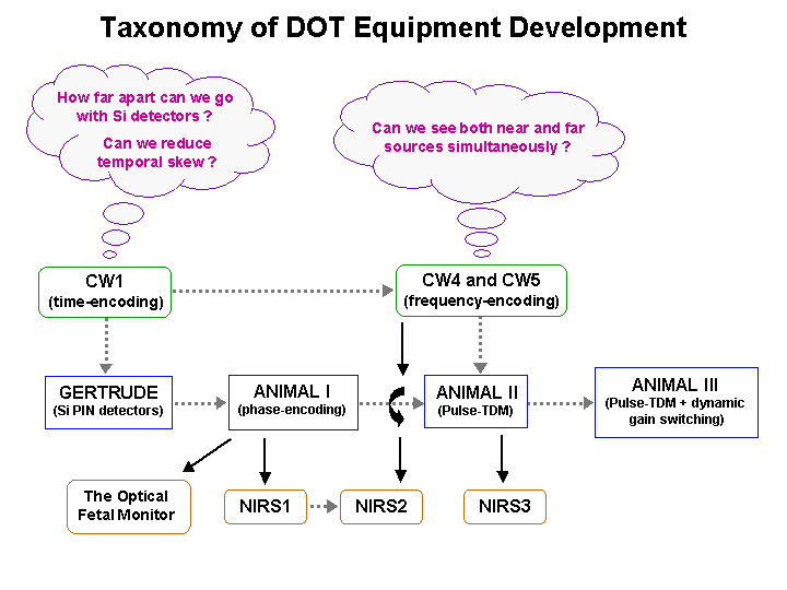
The development of hardware is an evolutionary process. Although revolutions (creative ideas, innovations) sometimes occur, the majority of design improvements occur slowly. Prototypes are built, lessons are learned, the design is changed, and performance improves. This ongoing cycle of improvement is sometimes referred to as “spiral development” – homing in on the performance goals by iteratively improving the equipment design in multiple steps. The DOT instrumentation in our laboratory evolved in a similar fashion. This section of the Web site discusses the evolution of CW DOT instrumentation over a period of many years – from the construction of the first CW imager to the development of the highly flexible, frequency encoded systems in use today. The chart below shows the general progression of the instrumentation, the innovation of each system and the questions addressed by each. Click on the appropriate box to read more about the each system.

All DOT instrumentation should be designed with the following parameters in mind: Large optode separations lead to significant optical attenuation, so multiple optode spacings will require a large dynamic range. The system should be as linear as possible over this dynamic range in order to keep the measurements both accurate and precise. Stray light rejection is important for systems that must operate outside of the sheltered confines of the laboratory, especially in clinical settings, which often contain large amounts of “optical pollution”. Both optical and electrical crosstalk should be reduced to levels commensurate with the system dynamic range, if possible. Good long-term stability means fewer and less frequent calibration cycles, and good temporal response is important for functional imaging, however it comes at the cost of an increase in the noise floor, which reduces dynamic range.