This shows how to fit a dipole using mne-python.
For a comparison of fits between MNE-C and mne-python, see:
Note that for 3D graphics you may need to choose a specific IPython backend, such as:
%matplotlib qt or %matplotlib wx
from os import path as op
import numpy as np
import matplotlib.pyplot as plt

import mne
from mne.forward import make_forward_dipole
from mne.evoked import combine_evoked
from mne.simulation import simulate_evoked

data_path = mne.datasets.sample.data_path()
subjects_dir = op.join(data_path, 'subjects')
fname_ave = op.join(data_path, 'MEG', 'sample', 'sample_audvis-ave.fif')
fname_cov = op.join(data_path, 'MEG', 'sample', 'sample_audvis-cov.fif')
fname_bem = op.join(subjects_dir, 'sample', 'bem', 'sample-5120-bem-sol.fif')
fname_trans = op.join(data_path, 'MEG', 'sample',
                      'sample_audvis_raw-trans.fif')
fname_surf_lh = op.join(subjects_dir, 'sample', 'surf', 'lh.white')
Let’s localize the N100m (using MEG only)
evoked = mne.read_evokeds(fname_ave, condition='Right Auditory',
                          baseline=(None, 0))
evoked.pick_types(meg=True, eeg=False)
evoked_full = evoked.copy()
evoked.crop(0.07, 0.08)

# Fit a dipole
dip = mne.fit_dipole(evoked, fname_cov, fname_bem, fname_trans)[0]

# Plot the result in 3D brain with the MRI image.
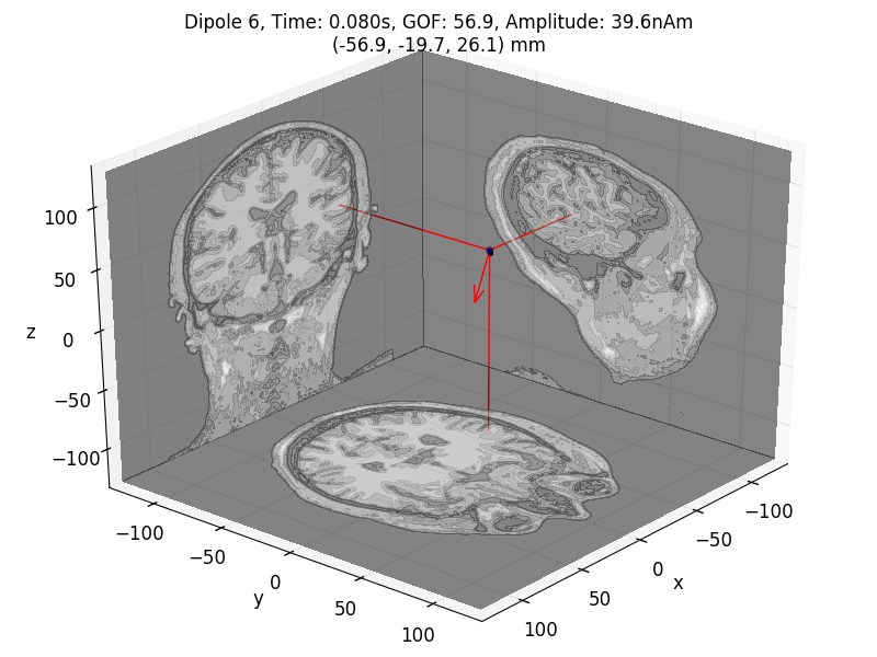
dip.plot_locations(fname_trans, 'sample', subjects_dir, mode='orthoview')

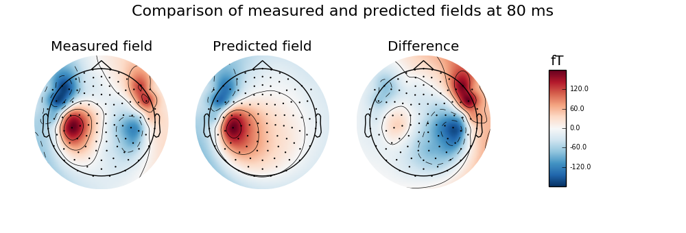
Calculate and visualise magnetic field predicted by dipole with maximum GOF and compare to the measured data, highlighting the ipsilateral (right) source
fwd, stc = make_forward_dipole(dip, fname_bem, evoked.info, fname_trans)
pred_evoked = simulate_evoked(fwd, stc, evoked.info, None, snr=np.inf)

# find time point with highes GOF to plot
best_idx = np.argmax(dip.gof)
best_time = dip.times[best_idx]
# rememeber to create a subplot for the colorbar
fig, axes = plt.subplots(nrows=1, ncols=4, figsize=[10., 3.4])
vmin, vmax = -400, 400  # make sure each plot has same colour range

# first plot the topography at the time of the best fitting (single) dipole
plot_params = dict(times=best_time, ch_type='mag', outlines='skirt',
                   colorbar=False)
evoked.plot_topomap(time_format='Measured field', axes=axes[0], **plot_params)

# compare this to the predicted field
pred_evoked.plot_topomap(time_format='Predicted field', axes=axes[1],
                         **plot_params)

# Subtract predicted from measured data (apply equal weights)
diff = combine_evoked([evoked, -pred_evoked], weights='equal')
plot_params['colorbar'] = True
diff.plot_topomap(time_format='Difference', axes=axes[2], **plot_params)
plt.suptitle('Comparison of measured and predicted fields '
             'at {:.0f} ms'.format(best_time * 1000.), fontsize=16)

Out:
Colorbar is drawn to the rightmost column of the figure. Be sure to provide enough space for it or turn it off with colorbar=False.
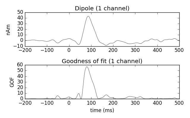
Estimate the time course of a single dipole with fixed position and orientation (the one that maximized GOF)over the entire interval
dip_fixed = mne.fit_dipole(evoked_full, fname_cov, fname_bem, fname_trans,
                           pos=dip.pos[best_idx], ori=dip.ori[best_idx])[0]
dip_fixed.plot()

Total running time of the script: ( 0 minutes 32.924 seconds)